 English
-
 English
 -
 Español
 -
 Português
 -
 русский
 -
 Français
 -
 日本語
日本語 -
 Deutsch
 -
 tiếng Việt
 -
 Italiano
 -
 Nederlands
 -
 ภาษาไทย
 -
 Polski
 -
 한국어
한국어 -
 Svenska
 -
 magyar
 -
 Malay
Malay -
 বাংলা ভাষার
 -
 Dansk
Dansk -
 Suomi
Suomi -
 हिन्दी
 -
 Pilipino
 -
 Türkçe
 -
 Gaeilge
 -
 العربية
 -
 Indonesia
 -
 Norsk
Norsk -
 تمل
تمل -
 český
český -
 ελληνικά
 -
 український
 -
 Javanese
 -
 فارسی
فارسی -
 தமிழ்
தமிழ் -
 తెలుగు
 -
 नेपाली
 -
 Burmese
 -
 български
 -
 ລາວ
ລາວ -
 Latine
 -
 Қазақша
 -
 Euskal
 -
 Azərbaycan
 -
 Slovenský jazyk
 -
 Македонски
 -
 Lietuvos
 -
 Eesti Keel
 -
 Română
 -
 Slovenski
The Placement of The Capacitors on The Power Circuit Board, Have You Placed Them Correctly?
2023-04-11
The power chip is indispensable on the circuit board. We generally use a large capacitor (100 µF to 1000 µF) and a small capacitor (0.1 µF or 0.01 µF) as the filter capacitors of the power supply.
Large capacitors are used to filter out low frequency noise, and small capacitors are used to filter out high frequency noise.
You have designed so many circuit boards. Are you placing the capacitors on the circuit board correctly?
Large capacitors are used to filter out low frequency noise, and small capacitors are used to filter out high frequency noise.
You have designed so many circuit boards. Are you placing the capacitors on the circuit board correctly?
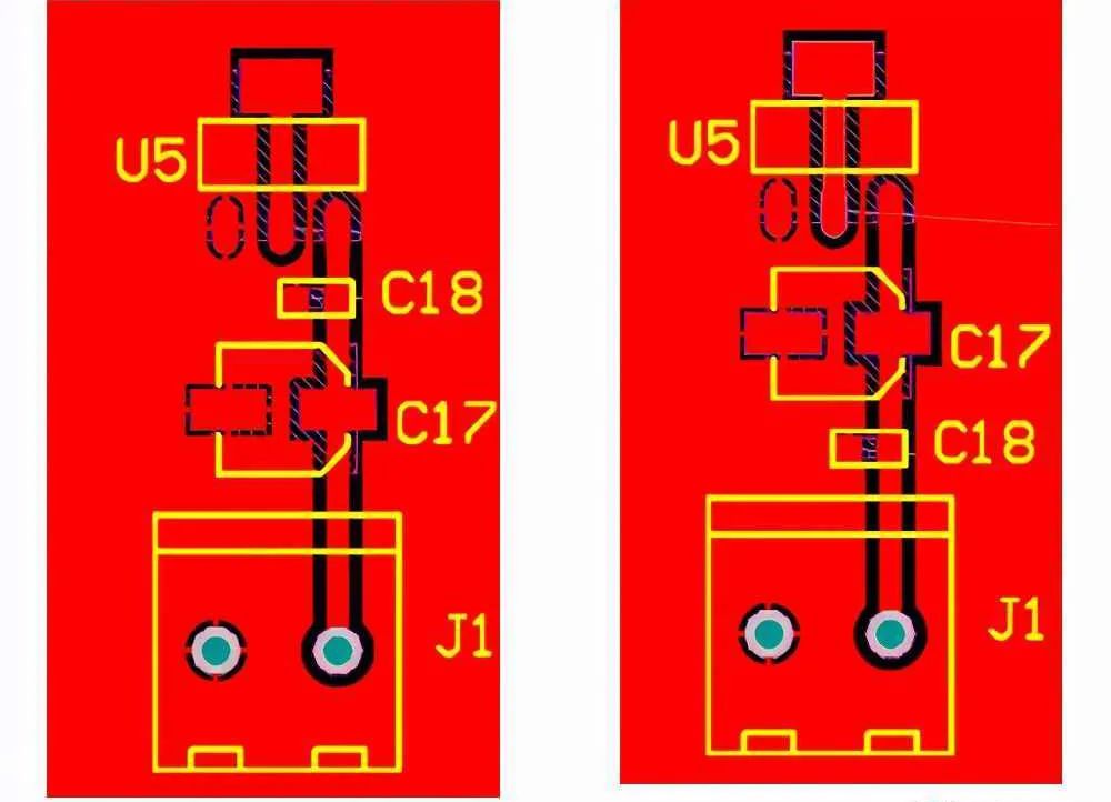
Let's first look at a set of PCB diagrams:

In this figure, the difference is that after the positive pole of the power supply comes in, the capacitor is too large or small.
The correct connection method is: first too large capacitor, then too small capacitor.
The picture on the left is correct.

In this picture, the difference between the left picture and the right picture is that the left picture is too large capacitor first, and then the small capacitor is too small.
The correct connection is shown on the left.
In general, any connection method can be used. In high-precision applications, in order to minimize the noise of the power supply, it is best to connect according to the correct method described above, and the filtering effect is the best.
The correct connection method is: first too large capacitor, then too small capacitor.
The picture on the left is correct.
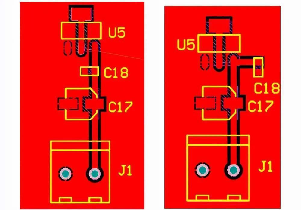
Let's look at a set of PCB diagrams:

In this picture, the difference between the left picture and the right picture is that the left picture is too large capacitor first, and then the small capacitor is too small.
The correct connection is shown on the left.
In general, any connection method can be used. In high-precision applications, in order to minimize the noise of the power supply, it is best to connect according to the correct method described above, and the filtering effect is the best.
X
We use cookies to offer you a better browsing experience, analyze site traffic and personalize content. By using this site, you agree to our use of cookies.
Privacy Policy


